I created it as a proof of concept and for fun.

How it works:
The milling script removes material by cutting the workpiece with the tool object (a rectangular box) in a simple Part.cut(tool) operation.The tool object position is determined by taking the last point and the next point from the path points list. Then, the script creates vector and walks through it by steps. At every step, the tool cuts the workpiece, and every 4 steps, the document is refreshed. Refreshed means the command Part.show(workpiece). Because this command creates a shape every time is called, before Part.show(workpiece), the previous shape is removed.
Wild and dirty.
Creating toolpath:
The first thing we need is the list of points that the "tool" will follow.This list has the form:
points = ( ( x,y,z ), ( x1,y1,z1 ), ... , ( xn, yn, zn), ( x,y,z ))
But manually creating the points is not the most adequate way, at least for more-less complex or large toolpaths.
If we want to do something like this...

...it could take forever manually, so I wrote a pocket function instead:
from FreeCAD import Gui
from PyQt4 import QtCore
from FreeCAD import Base, Draft, Part
import math as mt

# Basical definitions
raw_size=(30,30,10)

Tool_radius = 0.5
Tool_heigh = 8.0
feed_rate = 10.0

# Path Generator

Program=[(-5,0,30)] # Start position

def pocket(V0,L,H):
  global Program, Tool_radius
  YCycles = int(mt.floor((L / (2*Tool_radius))/2))
  V0 = (V0[0] + Tool_radius, V0[1] + Tool_radius, Program[0][2])
  Program.append(V0)
  V0 = (V0[0], V0[1], H)
  Program.append(V0)
  for i in range(YCycles):
    V0 = (V0[0]+(L-2*Tool_radius), V0[1], H)
    Program.append(V0)
    V0 = (V0[0],(2*Tool_radius)+V0[1], H)
    Program.append(V0)
    V0 = (V0[0]-(L-2*Tool_radius),V0[1], H)
    Program.append(V0)
    V0 = (V0[0],2*Tool_radius+V0[1], H)
    Program.append(V0)
  V0 = (V0[0]+(L-2*Tool_radius), V0[1], H)
  Program.append(V0)
  V0 = (V0[0], V0[1], Program[0][2])
  Program.append(V0)
It generates a pocket with initial position (lower-right corner) V0(x,y,z), side length L and absolute deepness H.
An screenshot of pocket((2,2,15),25,8)

Imagine to create that zigzag pattern by hand.
The function pocket itself does not represent the points, just creates the list. To create the wire that represents the toolpath, I have coded this:
Wire_done = False  # wire end condition
i=0
while Wire_done == False:
  i+=1
  if i == len(Program):
    Wire_done = True
    break

  if i == 1: # Starts the wire by creating the first line
    Line0 = Part.makeLine(Program[i-1], Program[i])
    Wire0 = Part.Wire([Line0])
  else: #Creates the rest of the wire
    Line1 = Part.makeLine(Program[i-1],Program[i])
    Trajectory_Wire = Part.Wire([Wire0,Line1])
    Wire0 = Trajectory_Wire

TjWire = App.ActiveDocument.addObject("Part::Feature", "Trajectory")
TjWire.Shape = Trajectory_Wire  #
TjWire_UserName = TjWire.Label
FreeCADGui.ActiveDocument.getObject(TjWire_UserName).LineColor = (1.00,0.67,0.00)
It iterates over the points list (named Program) and generates the tool trajectory wire.
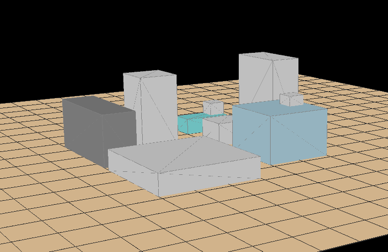
You can generate multiple pockets, this is the result of...

pocket((4,4,10),20,6)
pocket((8,8,10),10,3)
pocket((8,20,5),5,3)
pocket((15,20,5),5,3)
pocket((21,20,5),3,3)
pocket((10,10,5),5,2)

Create workpiece:
Raw = Part.makeBox(raw_size[0],raw_size[1],raw_size[2])
Raw_shape = App.ActiveDocument.addObject("Part::Feature", "Workpiece")
Raw_shape.Shape = Raw
Gui.ActiveDocument.getObject("Workpiece").Visibility=False
Create tool (the one that performs the cut):
Tool = Part.makeBox(Tool_radius*2, Tool_radius*2, Tool_heigh)
Tool_shape = App.ActiveDocument.addObject("Part::Feature", "Tool")
Tool_shape.Shape = Tool
Tool_shape_gui = Tool_shape.Label
FreeCADGui.ActiveDocument.getObject(Tool_shape_gui).ShapeColor = (0.33,0.33,1.00)

Tool_shape.Placement = App.Placement(App.Vector(Program[0]),ToolR )
Gui.ActiveDocument.getObject("Tool").Visibility=False
Create the animated tool:
AnimatedTool_shape= Part.makeCylinder(Tool_radius,Tool_heigh)
RTTH = Part.makeBox(Tool_radius/3.0, Tool_radius*2, Tool_heigh*1.1)

for i in range(5):
  alpha = i*360/5
  RTTH = Part.makeBox(Tool_radius/3.0, Tool_radius*2, Tool_heigh*1.1)
  RTTH.translate(Base.Vector((2*Tool_radius*mt.cos(mt.radians(i))/3.0,2*Tool_radius*mt.sin(mt.radians(i))/3.0,0)))
  RTTH.rotate(Base.Vector(0,0,0),Base.Vector(0,0,1), 15 + alpha)
  AnimatedTool_shape = AnimatedTool_shape.cut(RTTH)


AnimatedTool= App.ActiveDocument.addObject("Part::Feature","AnimatedTool")
AnimatedTool.Shape = AnimatedTool_shape
AnimatedTool_gui = AnimatedTool.Label
FreeCADGui.ActiveDocument.getObject(AnimatedTool_gui).ShapeColor = (0.33,0.33,1.00)
AnimatedTool.Placement = App.Placement(App.Vector(Program[0]), App.Rotation(App.Vector(0,0,1),0))
Pseudo-Mill core:
This is the function that performs the milling-like action:
Then, by calling repeatedly Machining() with a timer starts the animation:L1 = Raw.cut(Tool_shape.Shape) Part.show(L1) i=0 n=0.0 swd = 3 # cut refreshing interval s=0 def Machining(): global n, i,feed_rate, L1, Tool_radius, swd, s if i <= len(Program): Current_position = Tool_shape.Placement.Base Vector_trajectory = App.Vector(Program[i+1])-App.Vector(Program[i]) Vector_direction = (App.Vector(Program[i+1])-App.Vector(Program[i])).normalize() VT_modulus = Vector_trajectory.Length VD_modulus = 1.0 if VT_modulus > VD_modulus*n*feed_rate: Next_position = App.Vector(Program[i])+Vector_direction.multiply(n*feed_rate)+App.Vector(-Tool_radius, -Tool_radius) n+=0.1 else: Next_Position = App.Vector(Program[i+1]) i+=1 n=0.0 s += 1 if s > swd: App.ActiveDocument.removeObject("Shape") L1 = L1.removeSplitter() Part.show(L1) s = 0 Tool_shape.Placement = App.Placement(Next_position, ToolR) AnimatedTool.Placement = App.Placement(Next_position+App.Vector(Tool_radius,Tool_radius,0), App.Rotation(App.Vector(0,0,1),n*43)) L1 = L1.cut(Tool_shape.Shape)
With the tool-path created above this is the result:timer=QtCore.QTimer()timer.timeout.connect(Machining)timer.start(1)
What's next?
Well, I've been playing with creating the points list using a script that follows the contour of a FreeCAD part. That way you will only need to execute that script and then run the simulation.

Bye!