I started to study FreeCad Python Scripts yesterday and today I have managed to create a very simple script that builds up a very simple bearing. It can be used to figure how will it look in the assembly.
Let's code!
To accomplish this task we will need two libraries, Part and math.
The basic body of a conventional fixed ball-bearing can be built up in several ways. We are going to create 4 cylinders to achieve a very basic body.
Commands:
Import the libraries needed
import Part
import math
Now create the inner ring of the bearing with two cylinders (give your own values to variables):
B1=Part.makeCylinder(R1,TH) #B1=part name, R1=Cylinder radius, TH=Bearing thickness
B2=Part.makeCylinder(R2,TH) #As B1 (variable values in concordance)
At the moment we have created 2 cylinders. Maybe you ask where are them. Ok, when you create an object in FreeCad its view is not automatically refreshed, so if you want to see what is happening, just type:
Part.show(B1)
Let's do the boolean cut that will create the inner ring of the bearing. The next line creates a boolean cut of B1 and B2:
IR=B2.cut(B1)
Where IR="inner ring" new variable name. B2 part cutted by B1
if you run: Part.show(IR) you should see a ring like this:
Following the same path, we can build the outer ring:
B3=Part.makeCylinder(R3,TH)
B4=Part.makeCylinder(R4,TH)
OR=B4.cut(B3)
To solve getting the cylinders mixed with the rings, avoid Part.show() until all operations are finished.
Now a bit tricky part: the balls of the ball bearing.
The command to create a sphere is:
Ball=Part.makeSphere(RBall)
Ball is the name of that sphere and RBall the radius. This will create a sphere at (0,0,0) global coordinates system. Like this:
The balls of the ball bearing are not arranged in that position, so new command to move this:
Ball.translate(V)
That will move the sphere from (0,0,0) to the end of the V vector. To get this working:
V=(0,CBall,PBall)
Ball.translate(V)
CBall (Ball circle) is the radius of the ball ring, the distance between rings measured from (0,0,0).
PBall is the middle bearing thickness position (If TH=10, PBall=5)
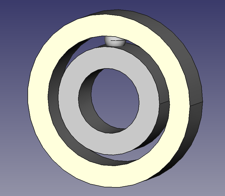
Running: Part.show(Ball) should show this:

Now we have the sphere in position. But we need more than just one to give this rough bearing a better looking.
Carefully, we can write this "for" loop that creates a number(NBall) of spheres in a equidistant position:
for i in range(NBall): #Starts loop
Ball=Part.makeSphere(RBall) #Creates a sphere called Ball
Alpha=(i*2*math.pi)/NBall #Gets angle between spheres and increases it every time a new sphere is created
BV=(CBall*math.cos(Alpha),CBall*math.sin(Alpha),TH/2) #Sphere translation vector to a given alpha value
Ball.translate(BV) #Translation
Part.show(Ball) #Screen refresh
This bucle contains the complicated math part, but the concept is very easy:
Create a ball, move it to its position and increase the angle of the position vector.
The result:
Just a dummy bearing :D
Yes, not very useful at using Freecad, but as FC-python introduction it does the job (I think)
Full code:
import Part
import math
#VALUES#
R1=15.0
R2=25.0
R3=30.0
R4=40.0
TH=15.0
NBall=10
RBall=5.0
#Program#
B1=Part.makeCylinder(R1,TH)
B2=Part.makeCylinder(R2,TH)
IR=B2.cut(B1)
B3=Part.makeCylinder(R3,TH)
B4=Part.makeCylinder(R4,TH)
OR=B4.cut(B3)
Part.show(IR)
Part.show(OR)
CBall=((R3-R2)/2)+R2
PBall=TH/2
for i in range(NBall):
Ball=Part.makeSphere(RBall)
Alpha=(i*2*math.pi)/NBall
BV=(CBall*math.cos(Alpha),CBall*math.sin(Alpha),TH/2)
Ball.translate(BV)
Part.show(Ball)
And this is all I know at the moment about FreeCad scripts. The next step is to
round the ring edges to get a more realistic look:
I want to develop a tool that, with a shaft or hole selected, drafts down the bearing that better suits, using a database containing the measures of standard bearings.
Maybe too much ambition I think. Okay,
I did it :D
Freecad documentation is
poor or hidden and understand errors and commands take time.
I have tried to write this tutorial and explain things as easy as I could. But if you need more explanations, do not hesitate to contact me. But don not think I must know the answer, I am just new here ;).
Thanks for reading.